Processes are the collection of components that are used to build and represent business processes using BPMN 2.0 specification.
There are three concepts associated with modeling processes to understand and differentiate between:
-
Diagrams are the container that process definitions are modeled in. A process diagram can contain multiple process definitions when pools are used to separate them. Process diagrams are color coded with the following definitions:
- Blue indicates completed nodes
- Green indicates current active nodes
- Red indicates failed nodes
-
Process definitions are the templates that a process follows, made up of BPMN elements and sequence flows. A process definition describes the business logic that will be followed repeatedly at runtime.
-
Process instances are specific running instances of a process definition. Each process instance will have a unique process instance ID but they can share the same process definition ID indicating which process definition was used to start the process instance. There can be any number of process instances running using the same process definition in an N:1 relationship.
Create a process
To create a process:
-
Sign into the Modeling Application and open a project.
-
Click the NEW dropdown.
-
Select how to create the process:
-
Create > Process creates a new, empty diagram and process definition.
-
Upload > Process allows for uploading an existing diagram
.bpmn20.xmlfile into the Modeling Application.
Alternatively use the + or Upload buttons next to Processes in the left-hand menu.
-
-
Enter a name, optional description, and optional process category.
By default the name will be shared between the diagram and process definition and the description will apply to the process definition. If you enter a process category the process will be added under the process category heading in the left pane, and if the process category does not already exist it will be created. If you do not enter a process category name it will appear under the uncategorized heading.
Import a process from Process Services
Process diagrams exported from Alfresco Process Services can be imported into the Modeling Application by selecting the APS Process option when choosing to create a new process by importing an existing model.
The Process Service element types that are supported for import are:
| Process Services type | Process Automation type | Notes |
|---|---|---|
| Script task | Script task | A script and a script task will be created for each script.
|
| User task | User task | A user task will be created for each user task.
|
| Mail task | Email service | An instance of the email service is created and an email service task is created for each mail task.
|
| REST call task | REST connector | An instance of the REST connector is created and a REST connector task is created for each REST call task.
|
Diagrams
Diagrams hold one or more process definitions. If multiple process definitions are modeled within a diagram it is important to remember that the scope of each is restricted and the only way to communicate between them is via message or error events.
Diagram properties
The properties for a diagram are:
| Property | Description |
|---|---|
| ID | Required. The unique identifier for a diagram. This is system generated and cannot be altered, for example model-1bf32338-2bc2-4af2-9496-e9a031e22142 |
| Diagram name | Required. The name of the diagram. Diagram names must be in lowercase and between 1 and 26 characters in length. Alphanumeric characters and hyphens are allowed, however the name must begin with a letter and end alphanumerically, for example requests-and-orders. |
Diagram XML
The ID and name of a diagram are set as XML attributes of the definitions element, for example:
<bpmn2:definitions id="model-1bf32338-2bc2-4af2-9496-e9a031e22142" name="requests-and-orders">
Process definitions
Process definitions are designed using BPMN elements which in turn can reference other modeled components within a project such as forms, connectors and decision tables.
A process definition is created when a diagram is created and it will share the same name as the diagram. Use the BPMN element pools to create separate process definitions within a diagram.
Process definition properties
The properties for a process definition are:
| Property | Description |
|---|---|
| Process ID | Required. The unique identifier for a process definition. This is system generated and cannot be altered, for example Process_1w18m9x. |
| Process definition name | Required. The name of the process definition. Process definition names must be between 1 and 26 characters in length, they can also contain spaces, numbers, and consist of lower and upper case letters, for example Request Process. |
| Executable | Required. If set as false then the process definition will be deployed at runtime but it will not be possible to create any process instances using it. The default value is true. |
| Documentation | Optional. A free text description of what the process definition does, for example A process to request stock orders. |
| Process Category | Optional. Enter a free text description of your process categories. When creating a process you can either create a new process category or select one you have already created that appears in the dropdown list. When you use the Diagram Editor you can see the process category a process is assigned to under the Category property heading. |
Process definition XML
The ID, name and executable status of a process definition are set as XML attributes of the process element. Documentation is a sub-element of process, for example:
<bpmn2:process id="Process_1w18m9x" name="request-process" isExecutable="false">
        <bpmn2:documentation>A process to request stock orders</bpmn2:documentation>
Process modeling
The Modeling Application contains three tabs for creating and editing processes.
Diagram Editor
The Diagram Editor is the GUI for modeling processes by dragging and dropping items from the palette. The palette contains the BPMN elements that can be used to model a process and import other models created in the Modeling Application into a process. The palette also contains four tools for editing items on the canvas:
| Tool | Description |
|---|---|
| Hand | Use the hand tool to pan around the diagram and select elements to view their properties. |
| Global connect | Use the global connect tool to draw sequence flows between elements on the diagram. |
| Create/remove space | Use the create/remove space tool to move elements around the diagram. |
| Lasso | Use the lasso tool to drag a box and select multiple elements on the diagram. |
XML Editor
The XML Editor contains the XML for the process diagram. Changes made in the Diagram Editor or in the XML Editor are reflected in the other. When importing or downloading a process the .bpmn20.xml file will reflect what is in the XML Editor.
XML excerpts are provided as examples with each BPMN element.
Extensions Editor
The Extensions Editor is a JSON editor that stores any extensions made for process definitions. When a diagram contains more than one process definition, there will be an entry for each in the Extensions Editor. Extensions are broken down into four areas:
| Extension type | Description |
|---|---|
| constants | Constants are values that will not change for the duration of a process such as the service task implementation of a decision table. |
| mappings | Mappings are the record of how variables are passed between the process and other models and BPMN elements such as user tasks, decision tables and scripts. |
| properties | Properties store the details of process variables. |
| assignments | Assignments store the user and group assignations for user tasks. |
Process variables
Process variables are used to store values and pass them between BPMN elements throughout a process instance. For example, values entered into a form as part of a user task can be sent to process variables in the process, which in turn can send those values to a decision table to evaluate and choose the direction the process should take.
The scope of process variables is restricted to a process definition and not to the diagram it is created in, which is important to consider when using multiple pools.
Process variable properties
The properties for a process variable are:
| Property | Description |
|---|---|
| name | A unique name that can contain alphanumeric characters and underscores but must begin with a letter, for example var_3 |
| type | A data type selected from a dropdown. See the following table for a list of data types, for example String |
| required | Sets whether the process variable must contain a value when a process instance is started, for example false |
| value | An optional default value for the process variable, for example ice-cream |
Note: There are four process variable names that are created automatically and should not be used as custom process variable names.
nrOfInstances,nrOfActiveInstances,nrOfCompletedInstancesandloopCounterare used by multi-instance elements.
The data types that a process variable can be set as are:
| Type | Description |
|---|---|
| String | A sequence of characters, for example #Mint-Ice-Cream-4!. |
| Integer | A positive whole number, for example 642. |
| Boolean | A value of either true or false. |
| Date | A specific date in the format YYYY-MM-DD, for example 2020-04-22. You can also select Today from the Value column, which will take the form ${now()} in the Expression column. |
| Datetime | A specific date and time in the format YYYY-MM-DD HH:mm:ss, for example 2020-09-10 22:30:00. |
| File | A file uploaded into a process definition or as part of a process instance or task. |
| JSON | A JSON object, for example {"flavor" : "caramel"}. |
| Folder | A folder object described as JSON, for example "name": "mint-folder". |
| Array | A comma separated list of entries, for example mint, strawberry, vanilla that will be formatted to ["mint","strawberry","vanilla"]. |
Create a process variable
To create a process variable:
-
Select the project and process to create a process variable for in the Modeling Application.
-
Select Edit Process Variables against the correct process definition:
- If the diagram contains only one process definition, make sure no BPMN element is selected by clicking on a blank section of the canvas and the Edit Process Variables button will be visible in the right-hand properties panel.
- If the diagram contains more than one process definition then click on the individual pools to view the Edit Process Variables button for each definition.
-
Use the + symbol to add new variables and enter a name, type, optional value, and select whether it is required or not.
If you want the variable to be available in the Processes, and Tasks lists of the Digital Workspace click Yes below Available in the web application, and enter a display name. Once added to the Digital workspace you can select the new column by accessing the three dots on the top right.

Note: The details of any process variables can be viewed in the properties section of the extensions editor, for example:
{
    "properties": {
        "17aa41f7-9a0c-49c0-805b-045243f8a7e5": {
            "id": "17aa41f7-9a0c-49c0-805b-045243f8a7e5",
            "name": "firstName",
            "type": "string",
            "required": false,
        },
Process variable mapping
Mapping is a property of BPMN elements such as user tasks, service tasks and script tasks. It describes how data should be passed between a process and models such as forms, connectors, and scripts in a process. The data can be passed to variables within those models, such as form variables and script variables or other values in the model such as form fields, connector inputs and outputs and decision table inputs and outputs. Mapping this data is split between input mappings and output mappings:
-
Input mapping sets how and which data is sent from process variables to another model within the process.
-
Output mapping sets how and which data is sent from models within the process back to process variables.
There are five options for setting the Mapping behavior:
- Don't map variables
- Map variables
-
Process Variables are regular process variables that must match the type of the source or target parameter. For example an input parameter of type
stringcannot map to a process variable of typefile. -
Expressions: Expressions can be entered using a JSON editor to create more complex mappings such as mapping JSON process variables to input and output parameters. For example, using
${temperature.celsius}will use the value for the objectcelsius.In the following example this would result in a value of
16:{ "day": "Monday", "temperature": { "celsius": 16, "fahrenheit": 66 } } -
Static Values can be entered rather than using process variables.
- Map input variables
- Map output variables
- Map all variables
Don’t map variables is the default behavior.
When variables are not mapped, there is no transfer of data between process variables and other models within the process.
For example, if Don’t map variables is selected for a user task in a process then none of the form fields will be populated with values from earlier within the process instance. Similarly, when the form is completed none of the values entered by the user can be reused later in the process, such as within a decision table.
Map variables allows each input and output to be explicitly mapped between process variables and the values or variables within another model.
If Map variables is selected as the Mapping type, there are three ways of mapping variables that can be chosen by selecting the edit icon next to any input or output parameters:
An example of using the Map variables option is a decision table that contains the input Price and the output Decision and the process contains the process variables Total and customerResponse the mapping can be configured like the following:
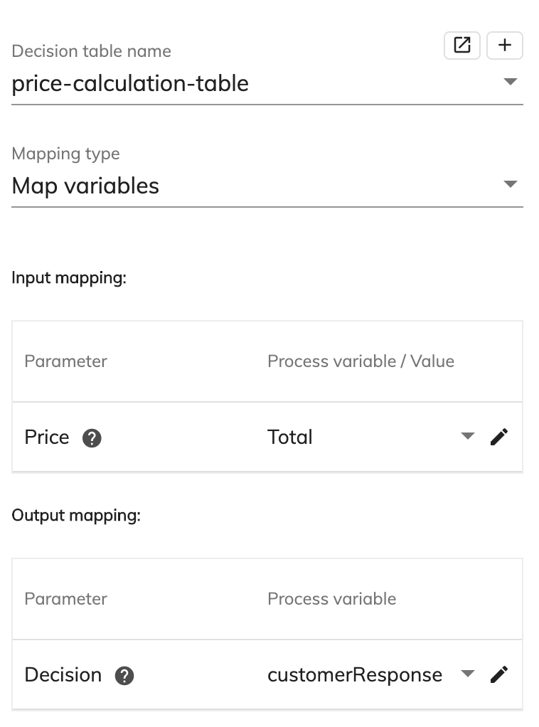
At runtime, the value for the process variable Total will be sent as the input to the decision table when that point in the process instance is reached. Once the decision table has evaluated the input, the value of the output Decision will be sent back to the process variable customerResponse which can then be used later in the process, such as in sending an email to a customer.
Map all input variables will automatically map the values of process variables to values or variables within a model if their names are identical. Outputs are not mapped at all, so there will be no transfer of data from the model, back to process variables.
For example, if Map all input variables is selected for an instance of the email service, process variables named to, subject and text can be used to automatically set the values for the recipient, subject and message in the connector. No output variables are required to be sent back to the process as the execution of the email service is always treated as successful.
Map all output variables will automatically map values or variables from a model to process variables in the process if their names are identical. If there is no process variable with a matching name to one of the outputs of the model it will be created when the model is executed using the name of the output value or variable. Inputs are not mapped at all, so there will be no initial transfer of data from process variables to the other model.
For example, if Map all output variables is selected for a start event that contains a form, the data entered to start the process can be used further in the process by mapping the values from fields within the form to process variables in the process. Process variables can be created during modeling time that use the same name as form fields, or alternatively they will be created automatically once the user task is completed at runtime.
Map all variables will automatically map the values of process variables to values or variables within a model if their names are identical. It will also map values or variables from a model to the process variables in the process if their names are idenitcal. Additionally, for output variables only, if there is no process variable with a matching name to one of the outputs of the model it will be created when the model is executed using the name of the output value or variable.
For example, if Map all variables is selected for a user task that contains an orderStatus field on the form, a process variable with the name orderStatus can be used to set the status of an order automatically when the user task is started. Before the task is completed, a user can update the orderStatus field on the form and it will update the same process variable when the task is finished with the new status. Additionally, all the other form fields will be created as process variables when the task is completed.
Any mapping configured in a process is stored in the Extensions Editor using the ID of the BPMN element. If not sending any variables then the ID of the element will not appear in the mappings section. The following is an example of explicitly mapping variables:
"mappings": {
    "Task_1f1wpht": {
    	"inputs": {
    		"flavor": {
    			"type": "variable",
    			"value": "choice"
    			},
    		"price": {
    			"type": "value",
    			"value": "${lookUp.price}"
    			},
    		"Limit": {
    			"type": "value",
    			"value": 200
    			}
    		}
    	}
    },
}
Capture assignee of completed task
You can use output mapping and the sys_task_assignee pre-defined variable to capture the assignee of a completed task. This is helpful because you could use the assignee information in another process. For example, you could use this in a support context where whoever the assignee of a completed task is could be the contact person for the account for which the task was carried out.
Note: The
sys_task_assigneevariable is a system variable and cannot be edited.
To create a process that captures the assignee of a completed task:
-
Create a form.
-
Create a process that includes a User task.
-
From the Properties pane select the form you created from the Form name dropdown list.
-
From the Mapping type dropdown list select Map variables.
-
Deselect the User task by clicking anywhere in the white space and then click Edit Process Variables from the right pane.
-
Click the + icon and enter a name for the process variable in the Name field.
-
From the Type dropdown list select Primitives then select string and then click Update.
-
Select your User task again and from the
sys_task_assigneedropdown menu under Output mapping select the process variable you have just created.
You now have a process that captures the assigned user of a completed task.
Errors
Errors are used by error catching events and error throwing events to model business exceptions using BPMN elements. They can be created and managed at the individual error event level, or at a diagram level. Unlike process variables, errors can be shared between process definitions in the same diagram.
To manage all errors in a diagram:
-
Make sure no BPMN element is selected by clicking on a blank section of the canvas and the Edit Errors button will be visible in the right-hand properties panel.
-
If the diagram contains more than one process definition then clicking on the individual pools will also show the Edit Errors button.
Messages
Messages are used by message catching events and message throwing events to send a message and optional payload between BPMN elements. They can be created and managed at the individual message event level, or at a diagram level. Unlike process variables, messages can be shared between process definitions in the same diagram.
To manage all messages in a diagram:
-
Make sure no BPMN element is selected by clicking on a blank section of the canvas and the Edit Messages button will be visible in the right-hand properties panel.
-
If the diagram contains more than one process definition then clicking on the individual pools will also show the Edit Messages button.
Actions
The actions that can be run against a process are:
| Action | Description |
|---|---|
| Save process diagram as SVG | Download the process diagram in svg format. |
| Download process | Download the .bpmn20.xml for the process. |
| Validate | Run validation against the process. Any errors can be seen in the log history at the bottom of the Modeling Application and are flagged in a pop-up box. |
| Save | Save any changes made on the process diagram. |
| Delete | Delete the process diagram. |
Edit User Task Notifications
Use the Edit User Task Notification window to edit the default email templates used for processes. You can configure the From and Subject fields for the selected user task so that at runtime they will send task email notifications that are not the default, to the assignee or candidate.
The fields on the Assignee tab and Candidate tabs are:
| Action | Description |
|---|---|
| From | Enter an email address that the task will be sent from. |
| Subject | Enter a message for the user that will recieve the notification. For example The task ${taskName} awaits your response. |
| Email template | Select the email template you want to use. You can select from the, Default email template, From file, From URL, and Create new email template. |
Edit Process Permissions
Use the Edit Process Permissions window to configure who can start a new process. The permission levels available are: Everyone can start it, Nobody can start it, or Specific users/groups can start it.